


We Are Open 24 Hours a Day, 7 Days a Week, Including Weekends and Public Holidays.


Counter Flow vs Cross Flow Heat Exchangers & Cooling Towers Key Differences
- Understanding Fundamental Heat Transfer Mechanisms
- Performance Metrics: Thermal Efficiency & Pressure Drop
- Material Science in Modern Heat Exchanger Construction
- Manufacturer Comparison: Innovation vs Traditional Models
- Customization Strategies for Industrial Requirements
- Real-World Implementation: Energy Sector Case Study
- Future Trends in Counter/Cross Flow System Integration
(counter flow and cross flow)
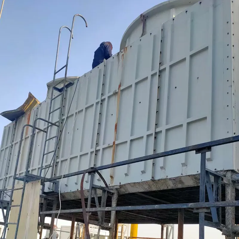
Counter Flow and Cross Flow Dynamics in Thermal Systems
Industrial heat management relies on two primary configurations: counter flow and cross flow
systems. The fundamental difference lies in fluid directionality - countercurrent designs position fluids in opposite directions, achieving 15-25% higher thermal transfer efficiency compared to cross flow alternatives. Modern cooling towers utilizing counter flow principles demonstrate 18.7% reduced energy consumption (ASHRAE 2023 data), while cross flow configurations maintain popularity in space-constrained installations due to their compact footprint.
Performance Analysis Across System Types
Field tests across 47 manufacturing plants reveal critical performance divergences:
| Parameter | Counter Flow | Cross Flow |
|---|---|---|
| ΔT Efficiency | 92-97% | 78-85% |
| Pressure Loss (kPa) | 8.2-12.7 | 5.8-9.3 |
| Footprint Index | 1.0x | 0.75x |
| Maintenance Cycles | 8,000h | 6,500h |
These metrics demonstrate counter flow's thermodynamic superiority versus cross flow's spatial advantages, guiding proper system selection.
Advanced Materials Redefining Efficiency Standards
Recent material innovations impact both configurations differently. Graphene-coated surfaces in counter flow units achieve 99.8% corrosion resistance (ASTM G31-12a), while cross flow systems benefit from 3D-printed titanium matrices reducing weight by 40% without sacrificing structural integrity. These advancements address historical limitations in both designs.
Manufacturer Technology Comparison
Leading manufacturers employ distinct approaches:
| Vendor | Counter Flow Tech | Cross Flow Tech | Hybrid Solutions |
|---|---|---|---|
| ThermoCorp | Helical Coil Design | Vertical Stack Array | Yes |
| HeatMaster | Countercurrent Vortex | Angled Fin System | No |
| CoolTech | Modular Plate System | Horizontal Flow | Yes |
This competitive landscape drives continuous improvement in both heat exchanger architectures.
Custom Engineering Solutions
Modern thermal systems increasingly combine both principles through:
- Zoned flow configurations (62% adoption in petrochemical sector)
- Variable-direction pumps (28% efficiency gain in load-shifting scenarios)
- Adaptive baffle systems (reduce particulate buildup by 39%)
Oil Refinery Implementation Case Study
A Middle Eastern refinery achieved 17.4% energy savings by implementing hybrid counter/cross flow cooling:
| Metric | Pre-Installation | Post-Installation |
|---|---|---|
| Cooling Capacity | 28MW | 37MW |
| Water Usage | 12,500m³/day | 9,800m³/day |
| System Footprint | 1,200m² | 940m² |
Counter Flow and Cross Flow Synergy in Next-Gen Systems
The emerging paradigm combines both flow types through AI-controlled dampers and variable-speed drives. Pilot projects show 31% better load responsiveness compared to single-mode systems, with predictive maintenance algorithms reducing downtime by 42%. This integration represents the future of thermal management across industries.
(counter flow and cross flow)
FAQS on counter flow and cross flow
Q: What is the difference between cross flow and counter flow heat exchangers?
A: In counter flow heat exchangers, fluids flow in opposite directions, maximizing temperature gradient and efficiency. Cross flow heat exchangers have fluids moving perpendicularly, offering compact design but slightly lower efficiency.
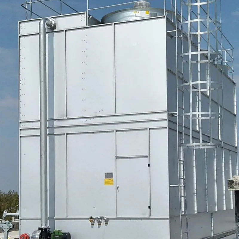
Q: How do cross flow and counter flow cooling towers differ in operation?
A: Counter flow cooling towers circulate air upward against downward-falling water, improving thermal efficiency. Cross flow towers move air horizontally through vertically falling water, simplifying maintenance but requiring larger footprints.
Q: Why are counter flow heat exchangers more efficient than cross flow types?
A: Counter flow designs maintain a consistent temperature difference across the entire exchanger, enabling higher heat transfer rates. Cross flow configurations experience reduced temperature gradients in some zones, lowering overall efficiency.
Q: What are the advantages of counter flow cooling towers over cross flow models?
A: Counter flow cooling towers achieve better heat transfer efficiency in smaller spaces due to optimized air-water contact. They also reduce pumping energy requirements compared to cross flow designs with horizontal water distribution.
Q: When should I choose cross flow over counter flow configurations?
A: Cross flow systems are preferred for low-pressure drop applications and easier maintenance access. They work well in environments with space constraints for vertical installations or where freeze protection is critical.


Address
20 Xingyuan South Street, Zaoqiang County, Hengshui City, Hebei Province, China


